Battery Systems
We have a range of DC to DC chargers, Low Volt Battery Cutouts and Smart Relays to suit a range of applications.
DC-DC Chargers vs Smart Relay Dual Battery Controllers
Newer vehicles (most manufactured after 2010) come with whats known as a smart alternator, or variable voltage alternator, as apposed to a fixed voltage alternator which comes as standard in older vehicles.
Fixed voltage alternators are becoming less common on new vehicles as reduced fuel consumption targets and stricter environmental and emissions standards are being followed by manufacturers. A fixed voltage alternator has a high enough voltage to charge a secondary battery in the vehicle to a usable level for leisure or auxiliary use.
The smart alternator system, also known as variable voltage alternators, allow the vehicle to control the output voltage and current from the alternator based on vehicle operating conditions. This is to reduce electrical load and in turn mechanical load on the engine by the alternator. Unfortunately, this renders it unsuitable for charging a secondary battery system to a usable level.
DC to DC Battery Chargers are Battery Chargers that gain there power from a DC Source such as your vehicle battery.
DC to DC Chargers are becoming more and more useful these days due to newer model car and truck alternators producing a much lower voltage then they used to, which is not suitable to charge deep cycle batteries to optimum levels.
The other commonly used scenarios are in Caravan / Campervan / Motorhome's to boost the voltage lost over long runs of cable from front of the car to the Caravan / Campervan / Motorhome's batteries. So by using a DC to DC Battery Charger you are able to boost this current to the correct voltage.
Enerdrive DC2DC Chargers
![]() In recent times Enerdrive has embarked on its own manufacturing program. They saw the need to control their own destiny and produce high-end products that the Australian market place was demanding.
In recent times Enerdrive has embarked on its own manufacturing program. They saw the need to control their own destiny and produce high-end products that the Australian market place was demanding.
This program has led to Enerdrive manufacturing its own range of ePOWER AC battery chargers & DC2DC battery chargers, alongside Lithium battery systems.
This product range is engineered to withstand the demanding applications in marine & mobile electrical systems.
Enerdrive ePOWER DC2DC 40+amp Battery Charger/ MPPT Reg
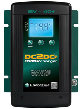 Designed to meet the rugged demands of Australian conditions and delivering multiple source charging for DC systems.
The Enerdrive ePOWER DC2DC+ Battery Charger is a fully automatic multistage, multi input battery charger with the ability to charge from either an alternator linked to a battery; or via solar power with the in built Maximum Power Point Tracking (MPPT) Solar Controller.
With two inputs available, the main/house battery will be charged from either the engine while underway, or via the solar panels when stationary. The process to choose either engine or solar is fully automatic and both functions are controlled from within the unit itself without the need for external relays.
During normal operation the ePOWER DC2DC+ Battery Charger will do a full charge cycle to float stage on the house battery bank with ability to choose either GEL, AGM, Flooded, Custom Programmable or Lithium. Once float stage is reached the charger transitions to a power supply mode to support any on-board DC loads.
The Enerdrive ePOWER DC2DC+ Battery Charger is a fully automatic multistage, multi input battery charger with the ability to charge from either an alternator linked to a battery; or via solar power with the in built Maximum Power Point Tracking (MPPT) Solar Controller.
Features:
- Two totally independent DC Inputs for both engine and solar regulation charging one house battery bank output
- DC M6 screw terminals that will allow for large battery cable connection between all sources
- A dedicated Maximum Power Point (MPPT) solar regulator
- The same battery algorithms as included in our AC mains ePOWER battery charger. GEL, AGM, Flooded, Lithium and the ability to create a full custom profile
- Vehicle input allows for either 12 or 24v and a maximum solar input of 45V/800W
- 40A+ output up to 40+°C with thermo controlled fan cooling
- Fully programmable LCD display to show which source is charging the battery along with charger status, voltage and amperage
- Temperature sensor included with charger for more accurate battery charging
Multistage Charging Process
The ePOWER DC2DC+ Battery Charger is a fully automatic, set and forget charger. It is designed to quickly and accurately recharge your deep cycle batteries utilizing charger algorithms that help to maximise the life of your specialised deep cycle batteries.
The ePOWER DC2DC+ Battery Charger features multistage smart charging technology that enables the charger to be connected to your battery bank permanently. With the input of multiple sources, you can be assured of charging your batteries whenever underway; or when the sun is shining on your solar array.
As dictated by battery manufacturer's recommendations, deep cycle batteries require a multistage charge sequence for perfect, fast and accurate charging. The Enerdrive ePOWER DC2DC+ smart charger delivers three primary charge stages.
Stage 1 - Bulk or Boost charge; The battery is charged at full rated output current of the charger until the battery reaches its final charging voltage, known as its absorption voltage. In this step, around 80% of the battery is recovered as fast as possible.
Stage 2 - Absorption Charge; With the charger voltage held steady, the remaining 20% is replaced with the charger allowing the current to taper off as the battery approaches full charge.
Stage 3 - Float; Finally, in the float stage the charger voltage is lowered and held at a constant and safe predetermined level. This prevents the battery from being overcharged, yet allows the charger to supply enough current to make up for the self-discharge losses of the battery, while supporting any additional loads connected to the battery (such as DC lighting and refrigerators). This stage allows for the charger to be used as a DC power supply.
 Smart Charging Feature
The ePOWER DC2DC+ Battery Charger will regulate its output based on the loads connected to your battery bank. This function is important to maintain the life of your battery bank as some battery chargers mistake loads for discharge and continue to keep the batteries in the bulk or absorption stage for extended periods of time, which will damage the battery bank. The ePOWER DC2DC+ Battery Charger has two methods of load based regulation to ensure your battery charger transitions to float when it should do so.
Output Voltage |
12V Nominal (8.0V min.) |
|---|---|
Output Current (Maximum) |
40A - 50A |
Output Power |
775W |
Charger DC Output (CH1):
|
|
Selectable Battery Type |
Gel, AGM, Flooded, Lithium, Program |
Charger Voltage Range |
13.8V - 15.5V |
Float Voltage Range |
13.0V - 13.8V |
Charger Current (User Selectable) |
5/10/15/20/25/30/35/40/45/50A (default 40A) |
Equalize Voltage (Flooded Battery) |
15.5V |
Equalize Charging Current |
10% of Bulk Current Setting |
Charging Control |
2 stage / 3 stage selectable (Default 3 stage) |
DC Output Bank |
Single |
Current draw from CH1 when not in use |
< 50mA |
Battery Temperature Setting |
Low/ Normal/ High (Battery Temperature Sensor Standard) |
Efficiency |
95% |
INPUT Rating (CH2 - MPPT Solar) |
|
Input Voltage |
14.5 - 45VOC |
Maximum Input |
<23V input, 500W (600W allowable) |
INPUT Rating (CH3 - Start/Alternator) |
|
Input Voltage |
10.5 - 16VDC / 21 - 32VDC |
Dimensions (H x W x D) |
242mm x 172mm x 74mm |
Unit Weight |
1.85 Kg |
Enerdrive ePOWER DC2DC 30amp / 24v Charger / MPPT Reg
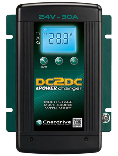 Designed to meet the rugged demands of Australian conditions and delivering multiple source charging for DC systems.
The Enerdrive ePOWER DC2DC+ Battery Charger is a fully automatic multistage, multi input battery charger with the ability to charge from either an alternator linked to a battery; or via solar power with the in built Maximum Power Point Tracking (MPPT) Solar Controller.
With two inputs available, the main/house battery will be charged from either the engine while underway, or via the solar panels when stationary. The process to choose either engine or solar is fully automatic and both functions are controlled from within the unit itself without the need for external relays.
During normal operation the ePOWER DC2DC+ Battery Charger will do a full charge cycle to float stage on the house battery bank with ability to choose either GEL, AGM, Flooded, Custom Programmable or Lithium. Once float stage is reached the charger transitions to a power supply mode to support any on-board DC loads.
The Enerdrive ePOWER DC2DC+ Battery Charger is a fully automatic multistage, multi input battery charger with the ability to charge from either an alternator linked to a battery; or via solar power with the in built Maximum Power Point Tracking (MPPT) Solar Controller.
Features:
- Two totally independent DC Inputs for both engine and solar regulation charging one house battery bank output
- DC M6 screw terminals that will allow for large battery cable connection between all sources
- A dedicated Maximum Power Point (MPPT) solar regulator
- The same battery algorithms as included in our AC mains ePOWER battery charger including a specific lithium charging profile
- 30A output up to 40+°C with thermo controlled fan cooling
- Fully programmable LCD display to show which source is charging the battery along with charger status, voltage and amperage
- Temperature sensor included with charger for more accurate battery charging
Multistage Charging Process
The ePOWER DC2DC+ Battery Charger is a fully automatic, set and forget charger. It is designed to quickly and accurately recharge your deep cycle batteries utilizing charger algorithms that help to maximise the life of your specialised deep cycle batteries.
The ePOWER DC2DC+ Battery Charger features multistage smart charging technology that enables the charger to be connected to your battery bank permanently. With the input of multiple sources, you can be assured of charging your batteries whenever underway; or when the sun is shining on your solar array.
As dictated by battery manufacturers recommendations, deep cycle batteries require a multistage charge sequence for perfect, fast and accurate charging. The Enerdrive ePOWER DC2DC+ smart charger delivers three primary charge stages.
Stage 1 - Bulk or Boost charge; The battery is charged at full rated output current of the charger until the battery reaches its final charging voltage, known as its absorption voltage. In this step, around 80% of the battery is recovered as fast as possible.
Stage 2 - Absorption Charge; With the charger voltage held steady, the remaining 20% is replaced with the charger allowing the current to taper off as the battery approaches full charge.
Stage 3 - Float; Finally, in the float stage the charger voltage is lowered and held at a constant and safe predetermined level. This prevents the battery from being overcharged, yet allows the charger to supply enough current to make up for the self-discharge losses of the battery, while supporting any additional loads connected to the battery (such as DC lighting and refrigerators). This stage allows for the charger to be used as a DC power supply.
Smart Charging Feature
The ePOWER DC2DC+ Battery Charger will regulate its output based on the loads connected to your battery bank. This function is important to maintain the life of your battery bank as some battery chargers mistake loads for discharge and continue to keep the batteries in the bulk or absorption stage for extended periods of time, which will damage the battery bank. The ePOWER DC2DC+ Battery Charger has two methods of load based regulation to ensure your battery charger transitions to float when it should do so.
Output Voltage |
24V Nominal (17.0V min.) |
|---|---|
Output Current (Maximum) |
30A |
Output Power |
865W |
Charger DC Output (CH1):
|
|
Selectable Battery Type |
Gel, AGM, Flooded, Lithium, Program |
Charger Voltage Range |
27.6V - 31.0V |
Float Voltage Range |
27.6V - 31.0V |
Charger Current (User Selectable) |
5 / 10 / 20 / 30A (default 30A) |
Equalize Voltage (Flooded Battery) |
31.0V |
Equalize Charging Current |
10% of Bulk Current Setting |
Charging Control |
2 stage / 3 stage selectable (Default 3 stage) |
DC Output Bank |
Single |
Current draw from CH1 when not in use |
< 50mA |
Battery Temperature Setting |
Low/ Normal/ High (Battery Temperature Sensor Standard) |
Efficiency |
95% |
INPUT Rating (CH2 - MPPT Solar) |
|
Input Voltage |
14.5 - 45VOC |
Maximum Input |
<23V input, 500W (600W allowable) >37.5V-45V input, 750W (800W allowable) |
INPUT Rating (CH3 - Start/Alternator) |
|
Input Voltage |
10.5 - 16VDC / 21 - 32VDC |
Dimensions (H x W x D) |
242mm x 172mm x 74mm |
Unit Weight |
1.85 Kg |
Intervolt Power Products
in![]() terVOLT provides electronic power solutions for DC applications in the transport market.
terVOLT provides electronic power solutions for DC applications in the transport market.
Consisting of specialised product for power conversion, control, conditioning and stabilisation - interVOLT has a reputation for quality, performance and value.
interVOLT products are designed, engineered and produced in Australia to cope with the demands of the harshest applications, particularly in high ambient temperature and high humidity environments.
They are constructed of quality materials, marine grade where applicable, and designed to provide many years of continuous service.
Intervolt DCC-Pro 25A DC-DC Charger
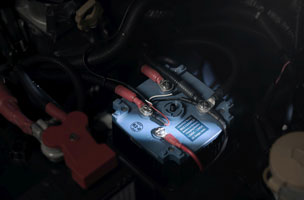
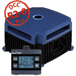 The DCC Pro In-Vehicle DC-DC Battery Charger was developed for the purpose of charging and maintaining any auxiliary battery in an installation where the starting battery is used as the supply source. It has been designed for use in 4WDs, RVs, buses, coaches, caravans, campers or any vehicle with a 12VDC electrical system.
The DCC Pro is built for our tough Australian conditions. Unlike many imported products, particularly those produced for the European market, it is designed to maintain output in the harshest of environments under the highest ambient temperatures.
The DCC Pro is a standalone power conversion device. It will manage a variety of different battery types according to their specific charging requirements. As no modification to the vehicle's original wiring is required this ensures the manufacturer's electrical system is not compromised in any way.
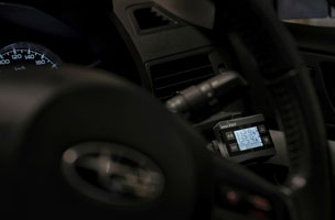
The DCC Pro is a highly innovative product with many unique features. It has the flexibility to adapt to almost any vehicle, old or new, simple or complex with or without an ECU controlled electrical system and even allows the operator monitor the charging status from the comfort of the cabin!
Features:
Following its release in 2015 the DCC Pro has enjoyed outstanding success in the overland vehicle market both in Australia and overseas. We are now pleased to introduce version 2.0 which features a number of functionality and performance upgrades offering even greater ‘value for money’ than the original.
Just some of the great features on the new DCC Pro 2.0:
- More Protection
Over-Voltage and reverse polarity protection on all Power Input Terminals. - Solar Charging
Make the most of the DCC Pros 25 amp output. Input wattage is now unlimited. The device itself regulates the output current which is limited to 25 Amps maximum with 3 stage charging from solar. - Charging State of Memory
A 30 minute ‘short stop’ timer has now been implemented. If the charge cycle is interrupted the DCC will resume as before providing it is within 30 minutes. - Proven Charging
Updated charging algorithms with new boost, absorption and float voltages. - LiFePO4 BMS Charging
Now incorporates Constant Current (CC) boost and Constant Voltage (CV) curve for boost and absorption stages for LiFePO4 batteries (with built in BMS only). - Longer Cable
4 metre lead as standard with the retail kit. - More information
Display now shows input type DC (main) or PV (solar) and charging stage. Alternate screen shows battery type
The best in-class performance for a charger of this size
The DCC Pro is a true 25 Amp Charger, that is, 25 Amps at 50°C all day, every day . In addition the DCC Pro will continue charging at reduced output right up to 85°C!!
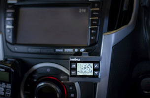
Remote monitoring from the comfort of the driving seat
The DCC Pro is fitted with an interactive, in-cabin display for remote monitoring of the auxiliary charging status from both main and solar power charging sources.
Solar ready – no need for a separate regulator or relay
The DCC Pro is a complete MPPT solar charge controller capable of handling 250 Watts of power with up to 30% greater efficiency than a standard PWM regulator.
Under bonnet charging device is dust and water proof
The DCC Pro is sealed to IP67 standard and is designed to be mounted in the engine bay or on the chassis itself. The DCC Pro can handle temporary submersion!
Capable of monitoring two chargers on a single display
The DCC Pro Remote Display can accept and monitor two Individual Charging Devices at once! No need to purchase a second display when two auxiliary batteries are used.
Input Voltage |
Main: 9-16 VDC, Solar: 18-28 VOC (open circuit Voltage - no load) |
|---|---|
Solar Power Input |
Unrestricted (System limited to 25 Amps) |
Continuous Rating |
25 Amps @ 50°C (de-rate from 50°C to 85°C) |
Current Draw - Charging Device: |
In stand by: Including LED indicator <10mA At full load: Up to 35 Amps |
Current Draw - Remote Display: |
With backlight off: 10mA max With backlight on: 45mA max |
Output Voltage - (Voltage values subject to tolerance ± 0.1V) |
Standard Lead Acid: Boost/CC: 14.5 VDC, Absorption/CV: 14.4 VDC, Float/CV: 13.4 VDC Absorbed Glass Mat: Boost/CC: 14.7 VDC, Absorption/CV: 14.6 VDC, Float/CV: 13.6 VDC Gelified Electrolyte: Boost/CC: 14.3 VDC, Absorption/CV: 14.2 VDC, Float/CV: 13.5 VDC Lead Calcium: Boost/CC: 14.9 VDC, Absorption/CV: 14.8 VDC, Float/CV: 13.8 VDC LiFePO4 BMS: Boost/CC: 14.6 VDC, Absorption/CV: -, Float/CV: 14.4 VDC |
Float Voltage |
13.2 VDC Nominal |
Electrical Protection |
Over temperature disconnect - auto re-connect Under Voltage shutdown - auto re-start High Voltage disconnect - auto re-connect Reverse polarity protection on all terminals |
Environmental Protection |
Charging Device: IP67 (internal components only) Remote Display: IP40 (not dust or water resistant) |
Operating Temperature |
-20°C to +85°C |
Operating Humidity |
Up to 100% (non-condensing) |
Charging Device Materials |
Heatsink: E-Coated ADC-3 die cast aluminium Blue Plastics: Temperature resistant PC/ABS alloy Black Plastics: 15% glass reinforced PBT Transparent Plastics: Temperature resistant PMMA |
Remote Display Materials |
Dark Grey Plastics: Temperature resistant PC/ABS alloy Transparent Plastics: Temperature resistant PMMA |
Terminal Material |
Tin plated brass |
Terminal Fasteners |
304 stainless steel |
Conformity |
AS/NZS CISPR 11:2004 for EMC |
Dimensions |
Charging Device: 112 x 112 x 75mm (including terminal cover) Remote Display: 60 x 36 x 59mm (including mounting bracket) |
Weight |
Charging Device: 690 grams Remote Display: 55 grams |
DCC-Pro Retail Pack includes the following items:
- DCC1225ACD - Automotive Charging Device 12 Volts DC 25 Amps
- DCC0001ARD - Automotive Remote Display complete with bracket
- DCC3000CTR - Data cable 4 metres charging device to remote display
There are longer leads available at additional cost
- DCC6000CTR - Data cable 6 metres charging device to remote display
- DCC9000CTR - Data cable 9 metres charging device to remote display
Intervolt Inertial Sense Module
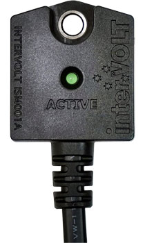 The Inertial Sense Module or ISM is a solid-state electronic device developed for use with the interVOLT DCC Pro.
In simple terms the ISM detects movement (from both engine vibration and acceleration) when attached to the vehicle chassis or body. Once the input voltage is within operating range this movement will provide a trigger signal to the DCC Pro and initiate the charging cycle.
This enables the DCC Pro to be operated in Ignition Mode without having to tap into the vehicle manufacturer's wiring system to obtain a signal. As a result, the whole DCC Pro install becomes totally independent of the vehicle's electrical system, aside from the common connection of the main battery terminals.
The ISM incorporates a short wiring harness (tail) which connects directly to the DCC Pro without any changes to the installation (if retrofitting) or any modification to the existing wiring harness.
The ISM is an over-moulded device rated to IP67 (dust and water proof) and can be fastened with the high-quality 3M tape included or via a single screw. Single screw fastening is recommended where vibration is minimal.
The compact size of the ISM allows it to be installed almost anywhere, within reach of the DCC Charging Device, of course. It is not recommended to extend the wiring harness but if Voltage Drop is factored in, it can be undertaken.
The ISM has a single LED indicator which will blink every 8 seconds in standby mode. Once activated by movement the LED will illuminate continuously until such time as the vibration/acceleration is no longer detected and the Voltage drops below the factory parameters.
| Design Voltage | 8 - 16 VDC |
|---|---|
| Switch On Voltage | 13.2V - 0.1V |
| Switch Off Voltage | 12.8V - 0.1V |
| Standby Current | 2 mA |
| Operating Current | 5 mA |
| LED Indicator | Green |
| Environmental Protection | IP67 |
| Operating Temperature | -20°C to +85°C |
| Weight | 30g |
| Dimensions | Footprint - 34mm x 38mm Profile - 12.5mm |
Dual Battery Systems
In a boat or vehicle with two battery banks, it is useful to be able to charge both banks while underway. Charge management devices allow two battery banks to be charged from a single source, such as an alternator, but keep batteries isolated when not charging. If one battery becomes depleted, there will be a charged bank available for emergency starting.
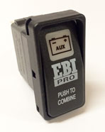
Intervolt EBI12100A Electronic Battery Isolator 12v 100A
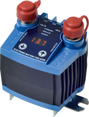 The EBI Pro is an electronic battery isolator aimed at replacing out-dated “electro-mechanical” type devices. Boasting features never before seen in dual battery isolators, the EBI Pro is designed to provide 4WD and RV users with real advantage and years of service.
Unlike conventional electro-mechanical isolators the EBI Pro is solid state. Solid state means no moving parts. There are no contacts to vibrate, chatter, arc, wear and ultimately - fail. The MOSFET based topology of the EBI Pro is proven. Reliability, durability and longevity are built in.
The solid state aspect is just the beginning. Designed on the back of the ground-breaking PSR, the EBI Pro is also adjustable in terms of voltage and time delay. This provides the installer or operator with the means to customise the EBI Pro for the application rather than suffer the ‘one size fits all’ philosophy from manufacturers of traditional devices.
These are expanded upon in greater detail in the manual but can be summarized as follows:
- Clear LED status display and indicators for ease of operation;
- 100 Amps continuously rated with a generous 500 Amps peak;
- Dual sensing allows main battery to be charged from auxiliary;
- Output indicator function for convenient in-vehicle monitoring;
- Input for in-vehicle remote emergency combine switch (starting);
- Overload and short circuit protection with automatic shutdown;
- Over temperature protected with automatic thermal shutdown;
- Low input voltage sensing with automatic shutdown protection;
- Electronics are encapsulated in dust and water proof housing;
- Compact design can be mounted in any position that suits;
- Heavy duty construction designed for under-bonnet installations;
- 24 months warranty (subject to policy terms and conditions).
Topology
|
Solid state Mosfet (metal oxide semiconductor field-effect transistor) switching circuit |
|---|---|
Application
|
12VDC in-vehicle dual battery installations only |
Input Voltage
|
8-17VDC nominal |
Control Voltage
|
The COMBINE (on state) voltage limits are user adjustable in 0.1 Volt increments from 9.2 Volts to 16.0 Volts |
Time Delay
|
Both the COMBINE and ISOLATE time delay limits are user adjustable in 1 second increments from 1 to 250 seconds |
Alert Voltage
|
The ALERT! voltage limits are user adjustable in 0.1 Volt increments from 9.0 Volts to 15.9 Volts |
Constant Rating
|
100 Amps DC continuous @ 60°C ambient temperature |
Surge Rating
|
500 Amps DC at <50°C for a period of 5 seconds @ 10% duty cycle |
Contact Resistance
|
Across switch terminals <2.0 milliohm @ 25°C |
Indicator Output Signal
|
30mA maximum (current limited) |
Device Current Draw
|
In 'Isolate' mode (open contacts) <30mA |
Environmental considerations
|
Operating temperature range is -25°C to + 60°C. Humidity should not exceed 90% |
Environmental Protection
|
Electronics sealed for dust and water protection to IP67 rating (internal components only) |
Safety and Protection Devices
|
Thermal overload shutdown – automatic reset |
User Interface
|
The user or operator interface is used to control and monitor the various functions of the EBI Pro. The user interface consists of a 3 digit LED display, 6 set point indicators and 2 control buttons. Refer to operator manual for detailed information on setting the EBI Pro parameters. |
Connections – Switch Terminals
|
Main (starting) battery positive – marked MAINBATT |
Connections – Control Terminals
|
Main negative input for sensing 0V – marked NEG |
Termination
|
Switch Terminals – M8 threaded stud, tin plated copper, 304 stainless steel hardware |
Construction |
Construction - Manufactured using corrosion resistant materials throughout. Electronics are epoxyencapsulated for protection against vibration, dust, water and for thermal dissipation purposes |
Conformity |
Conforms to Australian and New Zealand Electromagnetic Compatibility (EMC) |
Dimensions |
Footprint – 62mmW x 92mmL overall |
Weight |
495 grams |
Intervolt PSR Series DC Programmable Voltage Sensing Relays - PSR12150 & PSR24150
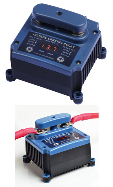 Voltage sensing relays have existed in one form or another for many years. They are commonly used to automatically replace the traditional manual process of controlling the charge function between batteries or battery banks, thus eliminating the risk of over/under charging.
interVOLT takes this process to a whole new level. The innovative design of the interVOLT PSR replaces traditional electro-mechanical relay devices used in 12/24 Volt DC applications by removing all mechanical parts to produce a completely solid state product with a myriad of added features.
In short, the PSR is a user adjustable voltage sensing relay in terms of voltage and time delay parameters. It allows the user to choose the voltage they want for switching loads on and off rather than be restricted to settings dictated by manufacturers. The time delay allows the relay to activate only after a user specified time to prevent cyclic (threshold) switching.
In addition the PSR is electrically isolated (contact to load), non-polarised and bi-directional, features previously unheard of in any other solid state relay devices. Additionally the PSR has the major benefit of being able to change from normally open or normally closed, all literally, at the touch of a button
The PSR can be used for a myriad of applications, including but not limited to:
- Combining of battery banks for charging and/or load sharing.
- Paralleling battery banks as emergency supplies.
- Switching loads at desired voltages both on and off.
- Protecting equipment from under-voltage supply.
- Isolating batteries at desired voltages both on and off.
- Safe and reliable remote switching of heavy loads.
Topology
|
Solid state Mosfet (metal oxide semiconductor field-effect transistor) switching circuit |
|---|---|
Application - 12 or 24 Volt DC installations. Voltage dependent models
|
12 VDC version model number PSR12150 |
Control Voltage
|
The upper and lower control voltage limits are user adjustable in 0.1 Volt increments from 9.0 Volts to 38.0 Volts (generic to both 12V and 24V models). |
Time Delay
|
The upper and lower time delay limits are user adjustable in 1.0 second increments from 001 to 255 seconds. |
Alarm Voltage
|
The upper and lower alarm voltage limits are user adjustable in 0.1 Volt increments from 9.0 Volts to 38.0 Volts (generic to both 12V and 24V models). |
Contact State
|
The contact state is user selectable for normally open (N/O) or normally closed (N/C). The factory default is normally open. |
Constant Rating
|
150 Amps DC continuous @ 40°C ambient temperature. |
Momentary Rating
|
500 Amps DC @ 40°C for a period of 10 seconds @ 10% duty cycle |
Input Voltage
|
Sensing: 9VDC Minimum, 38VDC maximum. |
Contact Resistance
|
For load terminals ≈0.5mΩ @ 25°C. Does not take into account connections i.e. terminal resistance. |
Alarm Output Signal
|
Equal to input voltage to 200mA maximum. |
Power Consumption (with LED display inactive)
|
Standby (un switched) – current draw is typically 10mA @ 13.5VDC for 12V systems and 23mA @ 27.0VDC for 24V systems. |
Environmental Considerations
|
Operating temperature range is -25°C to + 50°C. Humidity should not exceed 95 %. |
Environmental Protection
|
Electronics sealed for dust and water protection to IP67 rating (internal components only). |
Safety Devices
|
Thermal shutdown protection with automatic reset for over temperature. |
User Interface
|
The user or operator interface is used to control and monitor the various functions of the PSR. The user interface consists of a 3 digit LED display, 8 control (text) icons and 2 control buttons. The control icons are illuminated (flashing) when used in conjunction with the LED display and control buttons to adjust the desired parameters. Refer to operator manual for detailed information on setting the PSR parameters. |
Control Connections – for control and monitoring functions
|
|
Contact Connections
|
For load switching. Completely isolated from contact (sense) connections and are bidirectional and uni-polarity (not polarity conscious). |
Termination |
Load Terminals – M8 threaded stud, tin plated copper, 304 stainless steel hardware. – Control Terminals – M3 threaded contacts, tin plated brass, 304 stainless steel hardware. |
Construction – Manufactured using corrosion resistant materials throughout. No ferrous materials are used in the assembly. |
Housing – black electrophoretically coated A360 (ADC 3) die cast aluminium.
Cover, terminal protector and mounting feet insulators – ABS/ PC injection moulded plastics and stainless steel hardware. Fasteners – 304 stainless steel. |
Conformity |
Conforms to Australian and New Zealand Electromagnetic Compatibility (EMC) standards under AS/NZS CISPR 11:2004. |
Dimensions |
Footprint – 86mmW x 97mmL overall |
Weight |
505 grams |
Blue Sea m-Series Automatic Charging Relay - 12v/24v DC 65A
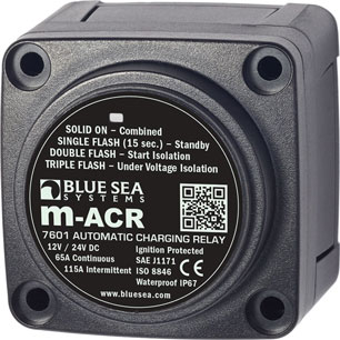 Automatically combines batteries during charging, isolates batteries during engine cranking and when not charging.
The Mini Automatic Charging Relay (M-ACR) is designed to manage the charging current from alternators up to 65 Amps found on most outboards and many inboard engines.
Start Isolation (SI) protects sensitive electronics by temporarily isolating house loads from the engine circuit during engine cranking, protecting the house circuit from voltage sags and spikes.
The compact design allows for three mounting styles: surface, rear, or panel mount. The M-ACR is also available as a module in a Custom 360 Panel.
Features:
- Senses charging on two battery banks
- Pull off and snap on insulating cover
- LED indicates ACR status
- 1 /4" x .032" male quick connect terminal for ground
- 7/ 16" (11 mm) stud length to accept multiple cable terminals
- Waterproof – rated IP67 for temporary immersion
- CE Approved
- ISO 8846 Marine Rated
- SAE J1171 Marine Rated
Nominal Voltage |
12V DC 24V DC |
|---|---|
Start Isolation* |
Yes |
Amperage Operating Current |
90mA (Combine) 15mA (Open) |
Continuous Rating** |
65A |
Intermittent Rating*** |
115A (5 min.) |
Cable Size to Meet Ratings |
6 AWG |
Maximum Cable Size |
1/0 AWG |
Terminal Stud Size |
1/4"-20 |
Terminal Stud Torque |
60 in-lb (6.78 Nm) |
Relay Contact Position |
|
Combine 30 sec. |
13.6V DC |
Open 10 sec. |
12.35V DC |
Open 30 sec. |
12.75V DC |
Open High |
16.0V |
Under Voltage Lockout**** |
9.5V |
Weight |
0.95lb (0.43 kg) |
* Condition: Engine starting
- Relay is open isolating batteries
- Batteries are isolated to protect sensitive electronics from voltage sags and spikes
** The maximum current a switch is designed to conduct for an indefinite period.
*** The maximum amount of current a switch is designed to carry for a minimum of a designated period of time.
**** As a safety feature, some ACR's prevent combining into a severely discharged battery. A dual-sensing ACR will monitor the voltage on both batteries and will not connect if either battery is below the under voltage lockout level. Use caution when combining into a battery with extremely low voltage, because this might represent a faulty battery or a problem elsewhere in the system.
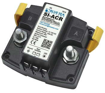
Blue Sea SI-ACR Automatic Charging Relay - 12v/24v DC 120A
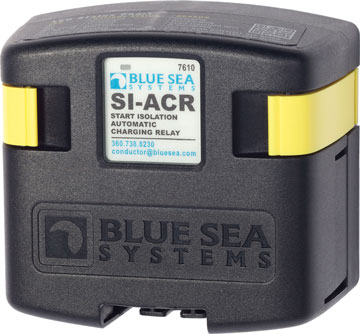 Automatically combines batteries during charging, isolates batteries during engine cranking and when not charging.
Features
- Protects sensitive electronics by temporary isolation of house loads from engine circuit during engine cranking
- Designed for 12 or 24 volt systems
- 12/24 volt auto ranging voltage input
- Hermetically sealed contacts/vapor proof
- Ignition protected—safe for installation aboard gasoline powered boats
- Supports high-output alternators up to 120 Amperes
- Dual sensing
- Waterproof – rated IP67 for temporary immersion
- CE Approved
- ISO 8846 Marine Rated
- SAE J1171 Marine Rated
- UL 1500 Approved
Optional Features
- Start Isolation allows temporary isolation of House loads from Engine circuit during engine cranking to protect sensitive electronics from sags and spikes
- Remote LED remotely indicates ACR states - requires optional LED
Nominal Voltage |
12V DC 24V DC |
|---|---|
Start Isolation* |
Yes |
Amperage Operating Current |
175mA (combined) 15mA (open) |
Continuous Rating** |
120A |
Intermittent Rating*** |
210A (5 min.) |
Cable Size to Meet Ratings |
1/0 AWG |
Terminal Ring Diameter Clearance |
1.12in (28.45 mm) |
Terminal Stud Length |
1.50in (38.1 mm) |
Terminal Stud Size |
3/8-16 (M10) |
Terminal Stud Torque |
140 in-lb (15.82 Nm) |
Relay Contact Position
|
|
Combine 30 sec. |
13.6V @ 12 V 27.2V @ 24 V |
Combine 90 sec. |
13.0V @ 12 V 26.0V @ 24 V |
Open 10 sec. |
12.35V @ 12 V 24.7V @ 24 V |
Open 30 sec. |
12.75V @ 12 V 25.5V @ 24 V |
Open High |
16.0V @ 12 V 30.0V @ 24 V |
Over Voltage Lockout |
16.0V @ 12V 32.0V @ 24V |
Under Voltage Lockout**** |
9.5V @ 12 V 19V @ 24 V |
Weight |
1.25lb (0.57 kg) |
* Condition: Engine starting
- Relay is open isolating batteries
- Batteries are isolated to protect sensitive electronics from voltage sags and spikes
** The maximum current a switch is designed to conduct for an indefinite period.
*** The maximum amount of current a switch is designed to carry for a minimum of a designated period of time.
**** As a safety feature, some ACR's prevent combining into a severely discharged battery. A dual-sensing ACR will monitor the voltage on both batteries and will not connect if either battery is below the under voltage lockout level. Use caution when combining into a battery with extremely low voltage, because this might represent a faulty battery or a problem elsewhere in the system.
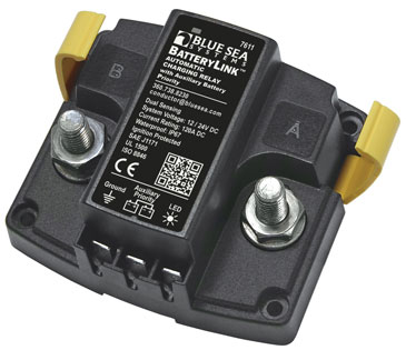
Blue Sea BatteryLink™ Automatic Charging Relay - 12v/24v DC 120A
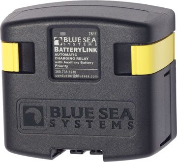 Automatically combines batteries during charging, isolates batteries during engine cranking and when not charging.
Features:
- 120 Amp continuous rating
- 12/24V DC auto ranging voltage input
- Senses charging on two battery banks
- Side and bottom knockouts for cable connections
- Clip-on cover insulates terminal connections
- 7/8" (22 mm) stud length to accept multiple cable terminals
- Integrated LED indicates ACR status
- 1/4" × .032" male quick connect terminals for ground and optional features
- Largest battery bank cannot exceed Group 27
- Waterproof – rated IP67 for temporary immersion
- CE Approved
- ISO 8846 Marine Rated
- SAE J1171 Marine Rated
Optional Features
- Optional Auxiliary Battery Priority connection shares the alternator charge with the Auxiliary battery longer when the engine is running to allow the use of auxiliary loads for an extended period of time
- Remote LED remotely indicates ACR states - requires optional LED
Nominal Voltage |
12V DC 24V DC |
|---|---|
Auxiliary Battery Priority* |
Yes |
Amperage Operating Current |
175mA @ 12V (Combine) 115mA @ 24V (Combine) 15mA (Open) |
Continuous Rating** |
120A |
Intermittent Rating*** |
210A (5 min.) |
Cable Size to Meet Ratings |
1/0 AWG |
Terminal Stud Size |
3/8-16 (M10) |
Terminal Stud Torque |
140 in-lb (15.82 Nm) |
Relay Contact Position
|
|
Combine 30 sec. |
13.6V @ 12V 27.2V @ 24V |
Combine 2 Min. |
13.0V @ 12 V 26.0V @ 24 V |
Over Voltage Lockout |
16.0V @ 12 V 32.0V @ 24 V |
Open Low |
12.75V @ 12 V 25.5V @ 24 V |
Auxiliary Priority
|
|
Open Low |
12.75V @ 12V 25.5V @ 24V |
Weight |
1.25lb (0.57 kg) |
* Condition Engine running:
- Open voltage is lowered to 12.25V from 12.75V
- Relay remains closed longer, combining batteries, to allow use of auxiliary loads for a longer period of time
** The maximum current a switch is designed to conduct for an indefinite period.
*** The maximum amount of current a switch is designed to carry for a minimum of a designated period of time.
ML-ACR Automatic Charging Relay - 12v & 24v DC - 500A
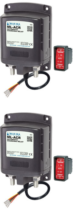 500 Amp magnetic latching (bi-stable) relay automatically combines batteries during charging and isolates batteries when discharging and when starting engine.
- Includes ML-Series Remote Control Contura Switch PN 2146
- Automatically manages the charging of two large battery banks
- Allows paralleling of battery banks for emergency starting
- 500 Ampere continuous rating to support high-output alternators
- Magnetic Latch (ML)—ACR draws very low current (<40mA to monitor terminal voltage) in the "ON" or "OFF" states, and draws moderate current for very short time when
- changing state
- Dual sensing—senses charge on both battery banks
- Start Isolation (SI)—can be configured for temporary isolation of House loads from Engine circuit during engine cranking to protect sensitive electronics
- Engine Isolation (EI)—can be configured for isolation of two engines while both are running to protect engine electronics and maximize alternator output
- Senses charging on two battery banks
- LED output to remotely indicate when batteries are combined, isolated, in voltage lockout, or in Start or Engine isolation
- 3/8"-16 tin-plated copper studs for maximum conductivity and corrosion resistance
- 7/8" (22mm) stud length accepts multiple cable terminals
- Silver alloy contacts provide high reliability for switching live loads
- Label recesses for circuit identification
- Waterproof – rated IP66 for temporary immersion
- CE Approved
- ISO 8846 Marine Rated
- SAE J1428 Marine Rated
Model |
7620 |
7621 |
|---|---|---|
Control Circuit Connection* |
Tinned Wire |
Tinned Wire |
Nominal Voltage |
12V DC |
24V DC |
Manual Control** |
No |
No |
Engine Isolation*** |
Yes |
Yes |
Mounting |
#10 |
#10 |
Start Assist**** |
Yes |
Yes |
Start Isolation***** |
Yes |
Yes |
Amperage Operating Current (@ 25°c nominal |
13mA |
13mA |
Amperage Operating Current when changing state |
<7.0A |
<7.0A |
Continuous Rating****** |
500A |
500A |
Intermittent Rating******* |
700A (5 min.) |
700A (5 min.) |
Cranking Rating 10 sec.******** |
2500A |
2500A |
Cranking Rating 1 min.********* |
1100A |
1100A |
Cable Size to Meet Ratings |
4/0 AWG x 2 |
4/0 AWG x 2 |
Live Current Switching |
300A @ 12V DC |
300A @ 12V DC |
Switching Cycles |
100000 |
100000 |
Terminal Ring Diameter Clearance |
1.12in (28.45 mm) |
1.12in (28.45 mm) |
Terminal Stud Length |
1.50in (38.1 mm) |
1.50in (38.1 mm) |
Terminal Stud Size |
3/8-16 (M10) |
3/8-16 (M10) |
Terminal Stud Torque |
140 in-lb (15.82 Nm) |
140 in-lb (15.82 Nm) |
Relay Contact Position
|
||
Combine 30 sec. |
13.5V |
27.0V |
Combine 90 sec. |
13.0V |
26.0V |
Open 10 sec. |
12.35V |
24.7V |
Open 30 sec. |
12.75V |
25.5V |
Open High |
16.2V |
32.4V |
Weight |
2.04lb (0.93 kg) |
2.08lb (0.94 kg) |
* Manual control switch provides an added level of safety allowing control with or without power, and offering LOCK OFF capability for servicing.
** Condition: Two engines are running
- One relay is open and one relay is closed
- Engine 1 Start and Engine 2 Start batteries are isolated to protect engine electronics
*** Condition: Engine starting
- Relay is closed combining batteries
- Batteries are combined to share power in the event of a low start battery
**** Condition: Engine starting
- Relay is open isolating batteries
- Batteries are isolated to protect sensitive electronics from voltage sags and spikes
***** The maximum current a switch is designed to conduct for an indefinite period.
****** The maximum amount of current a switch is designed to carry for a minimum of a designated period of time.
******* Normally associated with 'cranking current' which is the current required by the starter circuit prior to engine starting. The cranking current varies significantly during the starting cycle. Initially, there is a large surge of current required to overcome the inertia and compression of the engine. This surge can be two to four times the average cranking current. Once the engine is turning there are peaks and valleys as the pistons go through the compression and exhaust cycles. The cranking current rating is used for sizing batteries, cables, and battery switches.
******** The maximum amount of current a switch is designed to carry when starting an engine when the cranking period does not exceed 1 minute.
ML-ACR Automatic Charging Relay with Manual Control - 12v & 24v DC - 500A
500 Amp magnetic latching (bi-stable) relay automatically combines batteries during charging and isolates batteries when discharging and when starting engine.
- Manual control switch provides an added level of safety allowing control with or without power, and offering LOCK OFF capability for servicing
- Includes ML-Series Remote Control Contura Switch PN 2146
- Automatically manages the charging of two large battery banks
- Allows paralleling of battery banks for emergency starting
- 500 Ampere continuous rating to support high-output alternators
- Magnetic Latch (ML)—ACR draws very low current (<40mA to monitor terminal voltage) in the "ON" or "OFF" states, and draws moderate current for very short time when changing state
- Dual sensing—senses charge on both battery banks
- Start Isolation (SI)—can be configured for temporary isolation of House loads from Engine circuit during engine cranking to protect sensitive electronics
- Engine Isolation (EI)—can be configured for isolation of two engines while both are running to protect engine electronics and maximize alternator output
- Senses charging on two battery banks
- LED output to remotely indicate when batteries are combined, isolated, in voltage lockout, or in Start or Engine isolation
- 3/8"-16 tin-plated copper studs for maximum conductivity and corrosion resistance
- 7/8" (22mm) stud length accepts multiple cable terminals
- Silver alloy contacts provide high reliability for switching live loads
- Label recesses for circuit identification
- Waterproof – rated IP66 for temporary immersion
- CE Approved
- ISO 8846 Marine Rated
- SAE J1428 Marine Rated
Model |
7620 |
7621 |
|---|---|---|
Control Circuit Connection* |
Tinned Wire |
Tinned Wire |
Nominal Voltage |
12V DC |
24V DC |
Manual Control** |
Yes |
Yes |
Engine Isolation*** |
Yes |
Yes |
Mounting |
#10 |
#10 |
Start Assist**** |
Yes |
Yes |
Start Isolation***** |
Yes |
Yes |
Amperage Operating Current (@ 25°c nominal |
13mA |
13mA |
Amperage Operating Current when changing state |
<7.0A |
<7.0A |
Continuous Rating****** |
500A |
500A |
Intermittent Rating******* |
700A (5 min.) |
700A (5 min.) |
Cranking Rating 10 sec.******** |
2500A |
2500A |
Cranking Rating 1 min.********* |
1100A |
1100A |
Cable Size to Meet Ratings |
4/0 AWG x 2 |
4/0 AWG x 2 |
Live Current Switching |
300A @ 12V DC |
300A @ 12V DC |
Switching Cycles |
100000 |
100000 |
Terminal Ring Diameter Clearance |
1.12in (28.45 mm) |
1.12in (28.45 mm) |
Terminal Stud Length |
1.50in (38.1 mm) |
1.50in (38.1 mm) |
Terminal Stud Size |
3/8-16 (M10) |
3/8-16 (M10) |
Terminal Stud Torque |
140 in-lb (15.82 Nm) |
140 in-lb (15.82 Nm) |
Relay Contact Position
|
||
Combine 30 sec. |
13.5V |
27.0V |
Combine 90 sec. |
13.0V |
26.0V |
Open 10 sec. |
12.35V |
24.7V |
Open 30 sec. |
12.75V |
25.5V |
Open High |
16.2V |
32.4V |
Weight |
2.06lb (0.93 kg) |
2.10lb (0.95 kg) |
* Manual control switch provides an added level of safety allowing control with or without power, and offering LOCK OFF capability for servicing.
** Condition: Two engines are running
- One relay is open and one relay is closed
- Engine 1 Start and Engine 2 Start batteries are isolated to protect engine electronics
*** Condition: Engine starting
- Relay is closed combining batteries
- Batteries are combined to share power in the event of a low start battery
**** Condition: Engine starting
- Relay is open isolating batteries
- Batteries are isolated to protect sensitive electronics from voltage sags and spikes
***** The maximum current a switch is designed to conduct for an indefinite period.
****** The maximum amount of current a switch is designed to carry for a minimum of a designated period of time.
******* Normally associated with 'cranking current' which is the current required by the starter circuit prior to engine starting. The cranking current varies significantly during the starting cycle. Initially, there is a large surge of current required to overcome the inertia and compression of the engine. This surge can be two to four times the average cranking current. Once the engine is turning there are peaks and valleys as the pistons go through the compression and exhaust cycles. The cranking current rating is used for sizing batteries, cables, and battery switches.
******** The maximum amount of current a switch is designed to carry when starting an engine when the cranking period does not exceed 1 minute
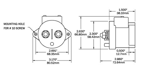
Blue Sea L Solenoid - 12/24V DC
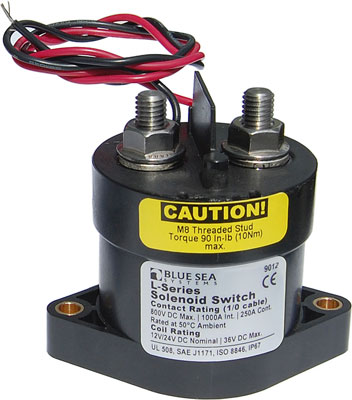
 Compact solenoid offers remote switching for applications with limited space where manual control is not required
- Hermetically sealed contacts / vapor proof
- Ignition protected - safe for installation aboard gasoline powered boats
- Activated by an ON-OFF switch mounted anywhere
- integrated coil control minimizes heating and amperage draw
- 450 Amp Class
- Designed for 12 or 24 Volt systems
- Ignition protected -- safe for installation aboard gasoline-powered boats
- Activated by a low amperage ON-OFF switch mounted anywhere
Control Circuit Connection* |
Tinned Wire |
|---|---|
Nominal Voltage |
12V DC 24V DC |
Coil Function** |
Normally Open |
Mounting |
#10 |
Operating Amperage Current |
3.8A when changing state |
Amperage Operating Current continuous |
0.13A @ 12 V 0.07A @ 24 V |
Continuous Rating*** |
250A using 1/0 wire size 300A using 2/0 wire size 400A using 4/0 wire size 450A using 2 x 2/0 wire size |
Intermittent Rating**** |
275A (5 min.) using 1/0 wire size 400A (5 min.) using 2/0 wire size 500A (5 min.) using 4/0 wire size 600A (5 min.) using 2 x 2/0 wire size |
Cranking Rating 10 sec.***** |
500A |
Contact Form |
SPST-NO |
Input Voltage |
9-36V DC |
Inrush Rating: 0.25 sec. (10 repeats) |
2000A |
Switching Cycles |
1,000,000 |
Terminal Stud |
Traditional Nut and Washer |
Terminal Stud Length |
0.625in (15.88 mm) |
Terminal Stud Size |
5/16" (M8) |
Terminal Stud Torque |
80 in-lb (9.04 Nm) |
Wire Leads |
22 AWG |
Weight |
1.00lb (0.45 kg) |
Blue Sea Add A Battery Kits - 120A & 65A
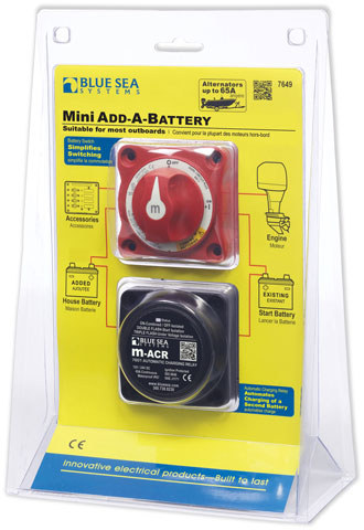
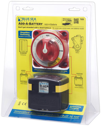 Don’t get stranded – Add a Battery!
Adding a second battery to the electrical system prevents the unintended discharge of the engine start battery.
Blue Sea Systems popular Add-A-Battery kit was primarily designed for boats with alternator output of 120A or less.
When installed, the Add-A-Battery isolates the start battery from the house loads which prevents the discharge of the start battery. The Add-A-Battery offers a simple way to control the charging and battery switching of two battery banks. The E-Series Dual Circuit Plus™ Battery Switch simplifies the switching while the SI-ACR automates charging between two batteries.
120A ACR |
65A ACR |
|
Nominal Voltage |
12V DC 24V DC |
12V DC 24V DC |
Start Isolation* |
Yes |
Yes |
Amperage Operating Current |
175mA (combined) 15mA (open) |
190mA (Combine) 15mA (Open) |
Continuous Rating** |
120A |
65A |
Intermittent Rating*** |
210A (5 min.) |
115A (5 min.) |
Cable Size to Meet Ratings |
1/0 AWG |
6 AWG |
Terminal Ring Diameter Clearance |
1.12in (28.45 mm) |
1.12in (28.45 mm) |
Terminal Stud Length |
1.50in (38.1 mm) |
|
Terminal Stud Size |
3/8-16 (M10) |
1/4" - 20 (M6) |
Terminal Stud Torque |
140 in-lb (15.82 Nm) |
60 in-lb (6.78 Nm) |
Relay Contact Position
|
||
Combine 30 sec. |
13.6V @ 12 V 27.2V @ 24 V |
13.6V @ 12 V 27.2V @ 24 V |
Combine 90 sec. |
13.0V @ 12 V 26.0V @ 24 V |
|
Open 10 sec. |
12.35V @ 12 V 24.7V @ 24 V |
12.35V @ 12 V 24.7V @ 24 V |
Open 30 sec. |
12.75V @ 12 V 25.5V @ 24 V |
12.75V @ 12 V 25.5V @ 24 V |
Open High |
16.0V @ 12 V 30.0V @ 24 V |
16.0V @ 12 V 30.0V @ 24 V |
Over Voltage Lockout |
16.0V @ 12V 32.0V @ 24V |
16.0V @ 12V 32.0V @ 24V |
Under Voltage Lockout**** |
9.5V @ 12 V 19V @ 24 V |
9.5V @ 12 V 19V @ 24 V |
Weight |
1.25lb (0.57 kg) |
0.95lb (0.43 kg) |
* Condition: Engine starting
- Relay is open isolating batteries
- Batteries are isolated to protect sensitive electronics from voltage sags and spikes
** The maximum current a switch is designed to conduct for an indefinite period.
*** The maximum amount of current a switch is designed to carry for a minimum of a designated period of time.
**** As a safety feature, some ACR's prevent combining into a severely discharged battery. A dual-sensing ACR will monitor the voltage on both batteries and will not connect if either battery is below the under voltage lockout level. Use caution when combining into a battery with extremely low voltage, because this might represent a faulty battery or a problem elsewhere in the system.
.jpg)
5511e |
6011 |
|
|---|---|---|
Switch Type |
Dual Circuit Plus |
Dual Circuit Plus |
Colour |
Red |
Red |
Switch Positions |
3 |
3 |
Battery Combine |
Yes |
Yes |
Alternator Field Disconnect* |
No |
No |
Maximum Voltage |
32V DC |
32V DC |
Continuous Rating** |
350A |
300A |
Intermittent Rating*** |
525A (5 min.) |
450A (5 min.) |
Cranking Rating 10 sec.**** |
1000A |
1000A |
Cranking Rating 1 min.***** |
750A |
650A |
Battery Inputs |
2 |
2 |
Cable Clearance For 4/0 AWG Cables |
1.10in (27.94 mm) |
1.12in (28.45 mm) |
Cable Size to Meet Ratings |
4/0 AWG (120mm²) |
4/0 AWG (120mm²) |
Mounting Holes |
Accept 1/4" (M6) Screw |
Accept #10 Screw |
Terminal Stud Size |
3/8"-16 (M10) |
3/8"-16 (M10) |
Terminal Stud Torque |
140 in-lb (15.82 Nm) |
120 in-lb (13.56 Nm) |
Weight |
1.30lb (0.59 kg) |
0.80lb (0.36 kg) |
* Alternator Field Disconnect: - Alternator Field Disconnect protects the diodes in the alternator in the event of the switch being switched to the OFF position while the engine is running. if the AFD is not used to protect the alternator, an LED can be connected to the AFD terminals to indicate when the battery switch is in any position but OFF.
** Continuous Rating: - The maximum current a switch is designed to conduct for an indefinite period.
*** Intermittent Rating: - The maximum amount of current a switch is designed to carry for a minimum of a designated period of time.
**** Cranking Rating 10 sec.: - Normally associated with 'cranking current' which is the current required by the starter circuit prior to engine starting. The cranking current varies significantly during the starting cycle. Initially, there is a large surge of current required to overcome the inertia and compression of the engine. This surge can be two to four times the average cranking current. Once the engine is turning there are peaks and valleys as the pistons go through the compression and exhaust cycles. The cranking current rating is used for sizing batteries, cables, and battery switches.
***** Cranking Rating 1 min.: - The maximum amount of current a switch is designed to carry when starting an engine when the cranking period does not exceed 1 minute.
Battery Low Voltage Disconnect
Low voltage disconnect switches are designed to protect batteries from excessive draw. Think of them as similar to circuit protection devices like fuses and breakers, but instead of terminating connection when voltage spikes, they disconnect when voltage drops too low, preventing damage to the batteries and load. To do this, a semiconductor switching circuit measures battery voltage; when it dips too low, predetermined auxiliary loads are switched off to ensure the battery has enough power left for engine starting.
This prolongs battery life by preventing damage due to excessive discharge and eliminates the need for separate timer or voltage sensing devices which simplifies wiring and installation and allows for a streamlined design.
Victron Smart BatteryProtect
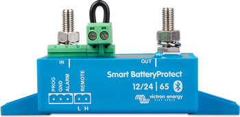 The Smart BatteryProtect disconnects the battery from non-essential loads before it is completely discharged (which would damage the battery) or before it has insufficient power left to crank the engine.
When using Bluetooth to program the Smart BatteryProtect any required engage/disengage levels can be set.
Alternatively, one of nine predefined engage/disengage levels can be set with the programming pin (see manual)
If required, Bluetooth can be disabled.
The Smart BatteryProtect is a uni-directional device. It can only deal with current in one direction, so either current to a load, or current from a charger, but not both currents at the same time. In addition to this, current only can only flow from the IN terminal to the OUT terminal. In case of use with a load, the battery connects to the IN terminal, and in case of use with a charger, the charger connects to the IN terminal.
A special setting for Li-ion batteries: In this mode the BatteryProtect can be controlled by the VE.Bus BMS.
Note: the BatteryProtect can also be used as a charge interrupter in between a battery charger and a Li-ion battery. See connection diagram in the manual
Maximum continuous load current* |
65A |
|---|---|
Peak current (during 30 seconds) |
250A |
Operating voltage range |
6 - 35V |
Current consumption |
BLE On: When on: 1.4 mA When off or low voltage shutdown: 0.9 mA BLE Off: When on: 1.2 mA When off or low voltage shutdown: 0.7 mA |
Alarm output delay |
12 seconds |
Maximum load on alarm output |
50 mA (short circuit proof) |
Load disconnect delay |
90 seconds (immediate if triggered by the VE.Bus BMS) |
Load reconnect delay |
30 seconds |
Default thresholds |
Disengage: 10.5V or 21V Engage: 12V or 24V |
Operating temperature range |
Full load: -40°C to +40°C (up to 60% of nominal load at 50°C) |
IP rating |
Electronics: IP67 (potted) Connections: IP00 |
Connection |
M6 |
Mounting Torque |
5 Nm |
Weight |
0.2 kg (0.5 lbs) |
Dimensions (H x W x D) |
40 x 48 x 106 mm |
Blue Sea m-LVD Low Voltage Disconnect
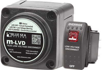 Senses low battery voltage and automatically disconnects devices to save power for starting or to preserve battery life
A dead battery is one of the most common reasons for a tow. Don't get stranded with a dead battery.
The m-LVD senses low battery voltage and automatically disconnects non-essential devices to save power for starting or to preserve battery life.
The m-LVD is ideal for any single battery boat or vehicle that wants to avoid getting stranded with a dead battery.
- Status light in both m-LVD and Remote Control Switch provides visual warning of low voltage state prior to disconnect
- Alarm output available for audible warning of low voltage state prior to disconnect (optional alarm required)
- Remote Control Switch Functions:
- Disconnect Voltage Adjustment - Sets desired disconnect voltage
- Override - Temporarily delays circuit disconnect for 10 minutes
- OFF - Temporarily disconnects circuits until voltage rises
- Override or OFF - Silences alarm (optional alarm required)
- Case design allows surface, front panel, or rear panel mounting
- Rear insulating cover protects rear contacts
- Waterproof - rated IP67 for temporary immersion
Nominal Voltage |
12V DC |
|---|---|
Amperage Operating Current |
95mA (Connected) 4mA (Open) |
Continuous Rating |
65A |
Intermittent Rating |
115A (5 Min.) |
Maximum Cable Size |
1/0 AWG (50mm2) |
Terminal Stud Material |
Tinned Brass |
Terminal Stud Length |
7/16 in (11.11 mm) |
Terminal Stud Size |
1/4" - 20 (M6) |
Terminal Stud Torque |
60 in-lb (6.78 Nm) |
Weight |
0.77lb (0.35 kg) |
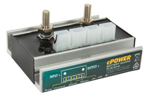
Enerdrive ePOWER Low Battery Cutouts
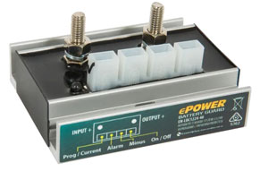
 The ePOWER Low Battery Cutoff protects your batteries from non essential loads before the battery is completely discharged causing damage to batteries and potently denying your engine cranking power. These Low Battery Cutouts also protect connected electrical appliances against over voltage. The voltage load is disconnected whenever the DC voltage goes beyond 16V (12V mode) or 32V (24V mode)
Microprocessor Controlled
The ePOWER LBC is microprocessor controlled with 10 different programs that engage or disengage the voltage load over several different voltage parameters.
Additionally, the ePOWER LBC range offers features like: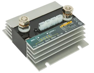
- Overvoltage Protection
- Ignition proof (no relay, no spark)
- Delayed alarm output
- Delayed load disconnect
Applications
- Recreational vehicles
- Service vehicles
- Maritime applications
EN-LBC1224-10 |
EN-LBC1224-40 |
EN-LBC1224-60 |
EN-LBC1224-200 |
|
Auto Voltage Detect |
8 - 20V -> 12 Volt Mode 20 - 35V -> 24 Volt Mode |
|||
Max Load (shut down current) |
10 - 15A |
40 - 45A |
60 - 65A |
200 - 210A |
Peak current |
75A @ 12V |
120A |
120A |
480A |
Under voltage disconnect voltage |
12 Volt Mode Adjustable starting from 9.5V 24 Volt Mode Adjustable starting from 19.5V |
|||
Over voltage disconnect voltage |
12 Volt Mode: 16V Cutoff 24 Volt Mode: 32V Cutoff |
|||
Current consumption |
Output Active: 4mA Output Inactive: 2mA |
|||
Shutdown at overload / short circuit |
After 5 seconds. (Switch on again 1 minute) |
|||
Weight |
20 g |
185g |
185g |
730g |
Dimension LxWxH |
62mm x 27mm x 9mm |
82mm x 65mm x 41mm |
82mm x 65mm x 41mm |
120mm x 112mm x 61mm |
Shutdown at overload / short circuit |
2% |
|||
Current accuracy |
20% |
|||
IP-code |
IP66 |
|||
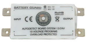
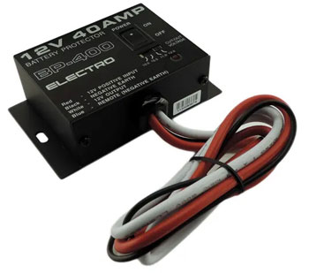
Electro Battery Protector 12V (40A)
 FEATURES
- Stop batteries from being over discharged
- Switches load on/off automatically
- Optional remote on/off feature
- Can also operate as a master switch for 12V circuits
- Used by many caravan OEMs
Model |
BP-400 |
|---|---|
Input (A) |
40A |
Input (V) |
12V |
Disconnect Voltages |
10V / 10.5V / 11V / 12V |
Reconnect Voltages |
Disconnect Voltage + 1V |
Weight |
0.4 kg |
Dimensions (L x W x H) |
85 x 70 x 35 mm |